COPPER PATCH CORDS BUYING GUIDE
Introduction
A patch cable refers to a type of short, flexible cable utilized for establishing connections between network ports, often found in horizontal copper cabling setups. The term "patch cable" originated from the early days of the telephone system, where operators at switchboards would "patch" calls between individuals. With the progression of the computer industry, cables facilitating network connections came to be known as patch cables due to their function of routing signals within a network.
Are all patch cables identical? No, there is a wide array of patch cable standards, technologies, and choices available today. Understanding these options is crucial as you will likely be responsible for selecting patch cables for your network. In many cases, network installers will not make the patch cable selection for you as they are unaware of your specific requirements such as cable length or color preferences, and budget constraints. Here is an overview of standards, technologies, and options to assist you in choosing the most suitable patch cable for your needs.
Patch Cable Standards
One of the most prominent features defining an Ethernet patch cable is its connector standard. All patch cables utilize the RJ-45 connector, also known as the male plug, on both ends. "RJ-45" denotes "registered jack," with "45" representing the interface standard. The RJ-45 plug comprises eight individual contacts and features a central locking tab resembling that of a large telephone cable.
Irrespective of the patch cable category, they all employ a stranded twisted four-pair round cable due to its enhanced flexibility compared to other cable types. This increased flexibility facilitates the organization of cable bundles within data cabinets or at the distant end of a horizontal cabling run, such as from the wall plate to the user's desk or docking station.
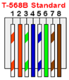
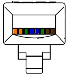
The stranded twisted four-pair round cable consists of four twisted pairs, each pair distinguished by specific colors for identification. These colored pairs include blue with white/blue, orange with white/orange, green with white/green, and brown with white/brown.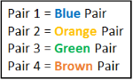
Setups from start to finish. In the illustration provided, the orange pair corresponds to pins 1 and 2 on the RJ-45 plug, the blue pair to pins 4 and 5, the brown pair to pins 7 and 8, and the green pair (sometimes referred to as the split pair) to pins 3 and 6.
The RJ-45 male plug and female socket are prevalent in Ethernet networking, adhering to a stringent standard with precise tolerances outlined in the IEC 60603-7 standard. This standard meticulously defines measurements and parameters to ensure that RJ-45 male plugs and female sockets align correctly, enabling dependable connectivity with minimal to no signal loss.
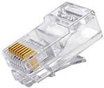
The RJ-45 plug features 8 gold-plated blades, known as "contact drivers," coated with 50-micron gold for reliable connectivity. Gold's resistance to oxidation ensures consistent electrical contact. With a gold thickness of 50 microns, the plugs can withstand up to 750 insertion cycles before wearing out. During termination, it's crucial to crimp the contact drivers within a height range of 0.232 to 0.242 inches from the plug base to ensure proper mating with RJ-45 female sockets and guarantee acceptable interoperability.
Patch Cable Technology
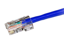
When considering patch cable technology, users frequently focus on the type of raw cable utilized, such as Category 5e or Category 6. However, the composition of the patch cable extends beyond just the raw cable. Significant technological components reside within the RJ-45 plugs positioned at each end of the patch cable. Similar to the raw cable, these plugs are categorized according to their internal designs, each tailored to achieve specific performance standards. In older Category 5 and 5e patch cables, a simpler one-piece RJ-45 plug design is utilized, accommodating the 8 individual wires arranged side by side in a 1 x 8 configuration. As depicted in the image below, the stranded cable enters the back of the plug on the right. Approximately midway through the plug, the 8 wires gradually align straight in the same plane as they approach and pass under the gold blade contact drivers. Consequently, for a brief distance within the plug, the four pairs remain untwisted. However, this characteristic doesn't compromise performance for these category-grade plugs, which are also easier to terminate.
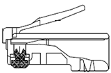
Category 5 Plug Body
Newer Category 6 and Category 6A plugs retain the familiar RJ-45 exterior shape, which cannot be altered. However, advancements are made within the internal cavity of the RJ-45 plug. These Category 6 and 6A plugs are more intricate, typically consisting of two or three parts. Upon inspection of the images provided, it's evident that these plugs feature a hollowed-out interior. This design element holds significant importance as it enables the 4 twisted pairs from the raw cable to remain closer to the gold blades without undergoing untwisting. Maintaining the twisted pairs in proximity to the gold blades enhances the performance of NEXT (Near End Crosstalk), an electrical measurement assessing noise from pair to pair within the cable.
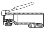


In Category 6 and 6A plugs, additional internal components include loading bars and pair separators. A loading bar, typically a small piece of plastic polymer with 8 holes, aids in keeping the 4 insulated pairs together during the termination of the cable assembly. Pair separators, another small plastic polymer piece, allocate each twisted pair to its designated quadrant, enhancing space and separation between adjacent pairs within the plug. This spacing improves NEXT performance in the final assembly, particularly for these higher data-grade plugs. Loading bars and pair separators may sometimes incorporate materials with metallic or dense properties to enhance cable performance. However, a drawback of Category 6 and 6A patch cables is that termination typically requires more time, resulting in higher assembly costs compared to Category 5e patch cables of the same length.
Another notable technical aspect of patch cable plugs involves arranging the 4 pairs. While the patch cable must adhere to the T568B wiring standard during termination, adjustments to the pair layout can be made to enhance performance. Category 5 and 5e plugs commonly employ a standard 1 x 8-row design, as performance requirements are less stringent for these cables. However, due to the heightened performance demands of Category 6 and 6A patch cables, a staggered or dual-plane design layout is often utilized in the plug. This wiring layout variation allows RJ-45 plug manufacturers to create additional space between pairs, resulting in improved NEXT performance within the patch cable plug.
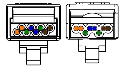
Typical Category 5 Wiring Layout Typical Category 6/6A Wiring Layout
Patch Cable Options
Patch cable options are typically the primary consideration for end users when acquiring patch cables, encompassing cable construction and appearance aspects. The range of patch cable options is extensive, offering choices such as cable construction, termination method, wire gauge, length, and color. Nowadays, patch cables have become a widely available commodity manufactured by numerous factories competing for consumer patronage. In this competitive landscape, many patch cable assembly houses strive to differentiate their products to attract customers, offering unique features or qualities to entice purchases.
Cable Construction
This forms the foundation of the raw cable selection for constructing patch cables, with typical options including stranded or solid wire, and jackets that are either unshielded or shielded, often with PVC or PLENUM ratings. While patch cables commonly consist of raw, unshielded cables with stranded wire and PVC jackets, specific scenarios may necessitate patch cables with solid wire, shielding, and plenum-rated jackets.
Termination Method
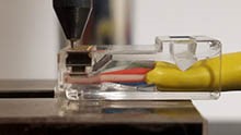
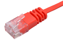
The choice of termination method is often a determining factor when purchasing patch cables. Various termination options exist, ranging from those with or without boots, assembled or molded types, and the availability of snaggles boots, as well as the option between slimline or standard width.
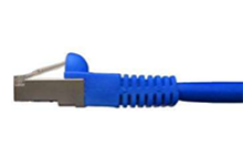
 Shielded, Slimline, Molded with Snaggles Boot Unshielded, Slimline, Molded Unshielded,
Assembled, with No Boot
Shielded, Slimline, Molded with Snaggles Boot Unshielded, Slimline, Molded Unshielded,
Assembled, with No Boot
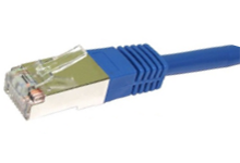
Shielded, Slimline with a Molded Termination Unshielded, Slimline, Molded with Snaggles Boot Unshielded, Assembled, with Snaggles Boot
Wire Gauge
The wire gauge inside a patch cable directly influences its performance. Typically, unshielded patch cables utilize 24 AWG stranded cables, while shielded patch cables opt for 26 AWG cables. However, the latest ANSI/TIA 568.2-D release acknowledges the use of smaller 28 AWG stranded cores in unshielded patch cables. Employing a smaller 28 AWG wire offers benefits such as space conservation, improved airflow, and enhanced port visibility in cable bundles. However, a drawback of 28 AWG is increased cable attenuation, necessitating the use of shorter cables to mitigate signal loss.
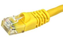
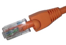
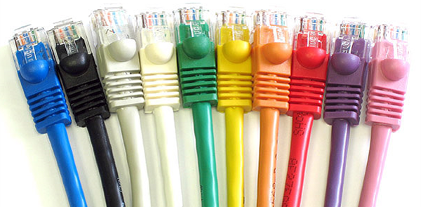
Length and Color
Irrespective of the cable's construction, most suppliers provide an extensive selection of cable lengths and colors. Length options usually span from 1 foot to 100 feet, with various increments available. Blue remains the predominant color choice, symbolizing data transmission. However, customers frequently opt for different colors to streamline networking ports across departments and security levels. Hence, it's commonplace for patch cables to be offered in a range of 8 to 10 different colors to cater to diverse organizational needs.
Conclusion
Although there's a wide array of patch cables available, the most common choice tends to be unshielded stranded PVC assemblies. While other variations exist, they are typically reserved for specific, specialized applications. Despite similar external appearances among different patch cable categories, the technology embedded within allows for support of higher-speed applications. Appearance also plays a significant role in selecting patch cables, with considerations such as termination method and color being crucial. Understanding patch cable category ratings, such as Category 5e, Category 6, and Category 6A, is essential as each supports different MHz ratings and applications. To delve deeper into Category 5 and Category 6 patch cables, refer to the Black Box Explains articles provided.
Check out AMP’s wide range of copper patch cords with all specifications and product details
BUYING GUIDES
Copper Patch Cords