COPPER CABLES BUYING GUIDE
Introduction
Ethernet LANs commonly utilize UTP cables, which consist of eight copper wires arranged in four twisted pairs. Each pair follows a color scheme, with one wire being solid colored and the other striped. RJ-45 connectors are typically found on both ends of a standard Ethernet UTP cable, accommodating the eight wires across eight pins. The arrangement of wires within these connectors determines whether the UTP cable functions as a straight-through or crossover cable.
Various cable types are necessary depending on the devices being connected, as certain devices send data through pins 1 and 2 while receiving through pins 3 and 6, while others transmit on pins 3 and 6 and receive on pins 1 and 2. Therefore, to link the transmitting pins of one device to the receiving pins of another, the appropriate cable type must be employed.
UTP Cabling Pinouts
To comprehend the contrast between the primary Ethernet cable types—straight-through and crossover cables—we need to grasp how different devices transmit electrical signals through their RJ45 ports. For instance, let's consider the rules governing the 10BASE-T and 100BASE-T Ethernet standards.
Initially, let's examine the initial set of devices, including Computers, Routers, and Wireless Access Points. These devices utilize pins 1 and 2 for transmitting data via electrical signals and the pair of pins located at positions 3 and 6 for receiving data.
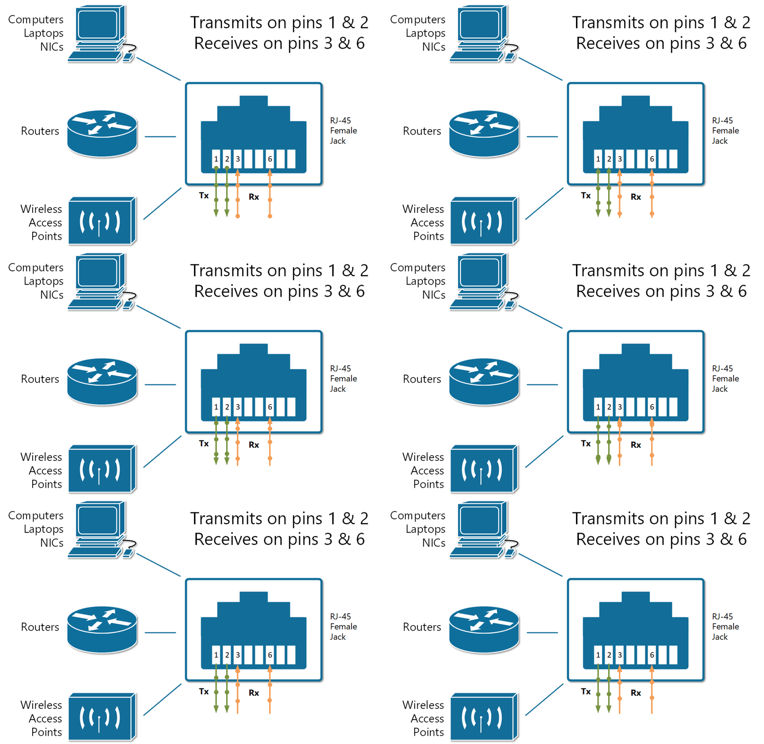
Figure 1 illustrates an RJ-45 port configuration where pins 1 and 2 are designated for transmission, while pins 3 and 6 are designated for reception. Devices utilizing this setup communicate over UTP copper cables according to these rules. Conversely, another set of devices including Ethernet hubs, bridges, and switches employ a reversed configuration, transmitting data via pins 3 and 6, and receiving data via pins 1 and 2. This arrangement contrasts with the configuration depicted in Figure 1.
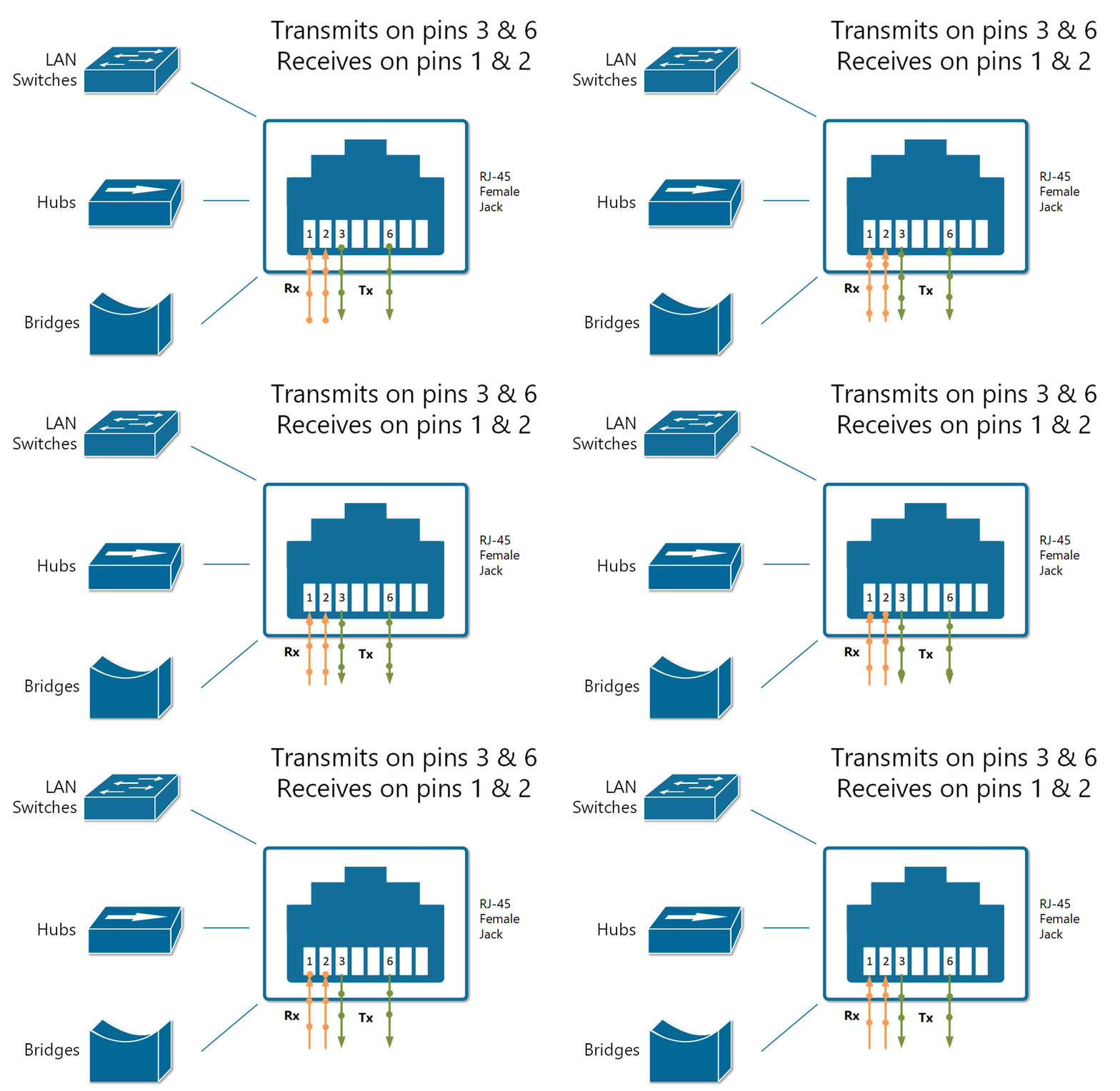
Figure 2. Devices that transmit on pins 3,6 and receive on 1,2
A straight-through cable directly links the wire from pin 1 on one end of the cable to pin 1 on the opposite end, ensuring a direct connection. Similarly, the wire from pin 2 connects straight to pin 2 on the other end, and the connection continues in this manner for all corresponding pins, as illustrated in Figure 3.
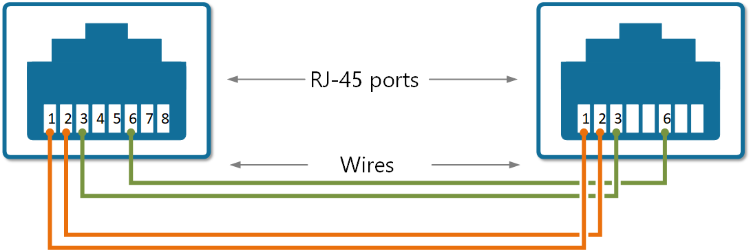
Figure 3. Straight-Through cable pinout
Now, consider the scenario where a device transmitting on pins 1 and 2 is connected to another device that receives on pins 1 and 2, such as a PC linked to a LAN switch using a straight-through UTP cable. As depicted in Figure 4, the connection functions seamlessly because the devices on the right utilize complementary pins for transmitting and receiving electrical signals, ensuring proper operation.
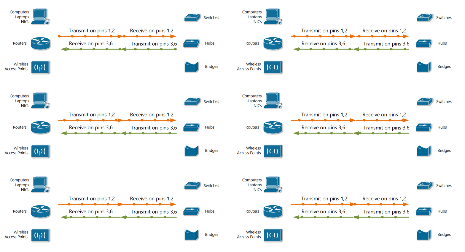
Figure 4. Straight-through cable is used between devices that transmit on opposite pairs of pins
However, let's consider the outcome of connecting two similar devices using a straight cable, as illustrated in Figure 5. For instance, they are connecting a router to another router or directly linking a computer's NIC card to a router. The diagram demonstrates the impact of the connection between these devices. Both routers transmit signals through the pair of pins 1 and 2, and they both receive signals through the pair of pins 3 and 6. Consequently, the transmitted signal from either end fails to reach the corresponding receiving end, resulting in communication failure.
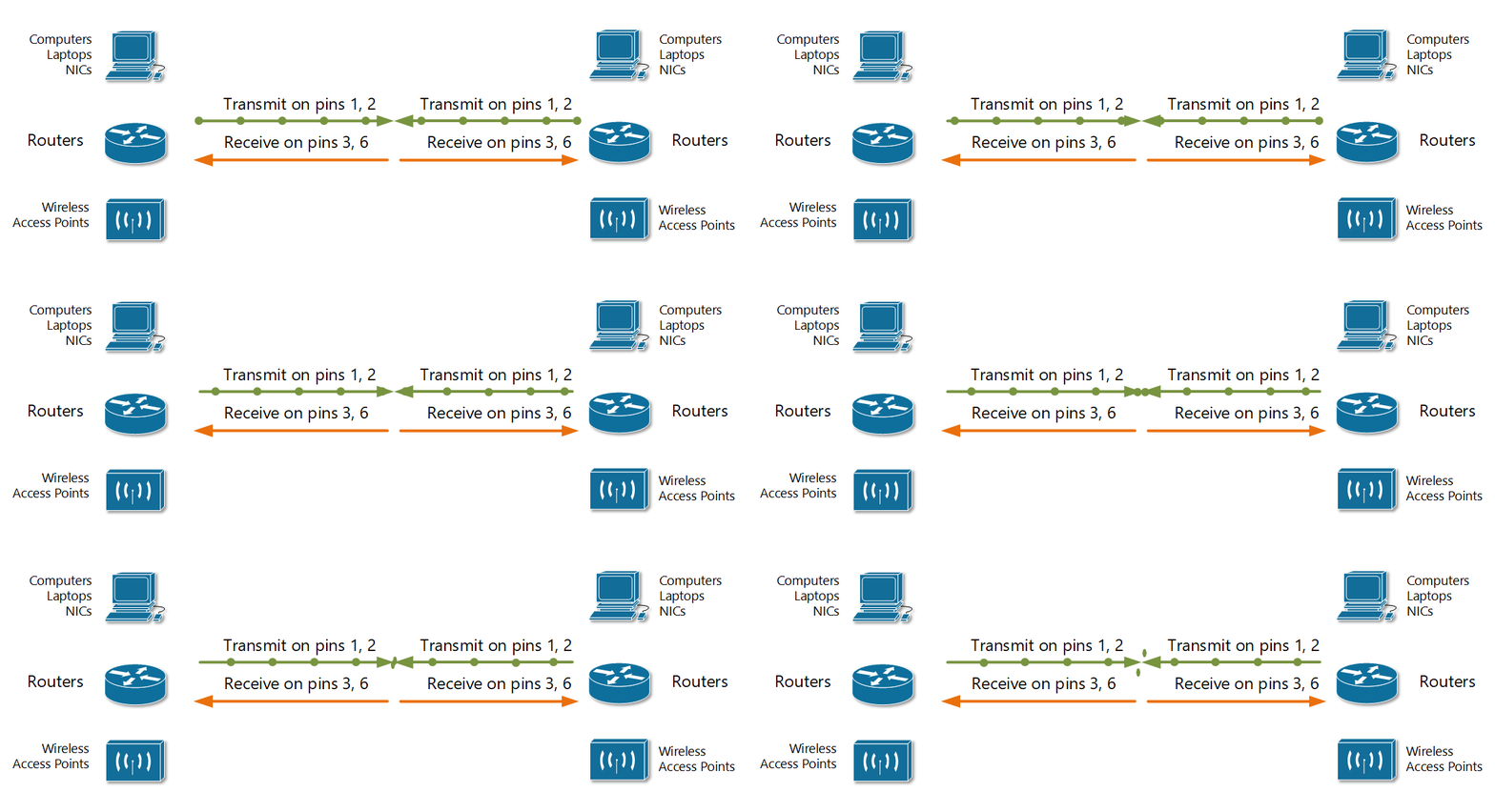
Figure 5. Straight-Through Cable used between devices that transmit on pins 1,2
To resolve this issue, the cable wires need to be crossed so that the transmitting pins on one end connect to the receiving pins on the opposite end, and vice versa. When some of the wires are crossed in this manner, the cable no longer maintains a "straight" configuration, hence it is termed a crossover cable.
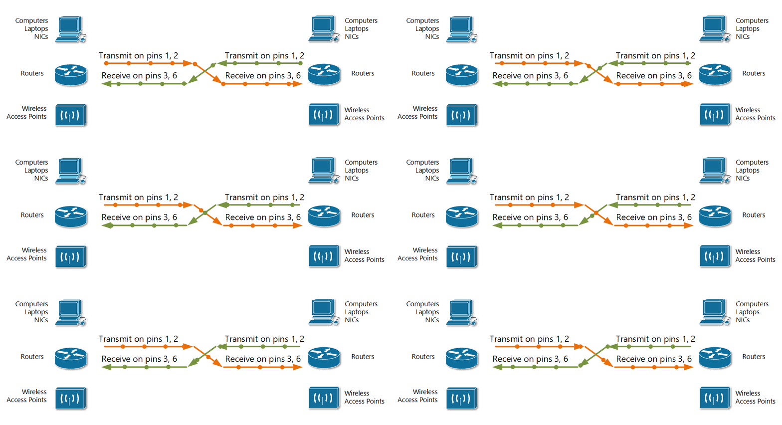
Figure 6. Using crossover cable between devices that transmit on pins 1,2
In essence, the decision on which cable to use for connecting Ethernet devices boils down to the following logic:
- Crossover cable: When both devices transmit using the same pin pair.
- Straight-through cable: When both devices transmit using different pin pairs.
Please note that in contemporary setups, connecting two Cisco devices using any cable will typically result in a functional link due to a feature known as auto-MDIX. This feature detects when an incorrect cable is used and adjusts the logic automatically to establish connectivity. However, for the CCNA exam, it remains essential to be able to distinguish whether the appropriate cable has been employed.
Example of using a wrong cable
Consider the following scenario illustrating the consequences of using an incorrect cable type to connect two devices when auto-MDIX is deactivated.
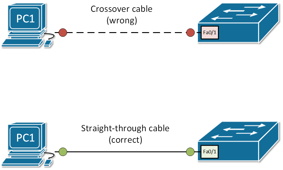
Figure 7. An example of using a wrong cable type
Summary
Ethernet cables are chosen based on their pinouts, as different devices utilize different pins for transmitting and receiving electrical signals through the RJ45 connector.
Two main types of copper cables exist: straight-through and crossover, distinguished by their pin configurations.
Straight-through cables are typically used to connect devices of different types, such as a PC to a switch.
Crossover cables are employed to link devices of the same type, for example, connecting one switch to another.
Modern network devices feature auto-MDIX functionality, which automatically detects cable types and adjusts transmitting and receiving pins as necessary for proper operation.
While it's generally recommended to use the correct cable type, accurately identifying the required cable for connecting specific sets of network devices is particularly crucial for success in the CCNA exam.